The wind uplift test
Flat roof Guidebook – Part 4
In the previous parts of the flat roof guidebook, the basics of planning a flat roof, the difference between flat and pitched roofs, the structure of a flat roof, ways of securing the position and the topic of pre-dimensioning were discussed.
The results of a wind uplift test can be valuable information for the creation of an initial sizing. But what does it mean and what information can it provide?
A wind suction test to determine the positional stability against wind loads on roof systems is referred to as the wind uplift test. With mechanically attached roof waterproofing systems, the failure load is specified in accordance with EAD or DIN 16002.
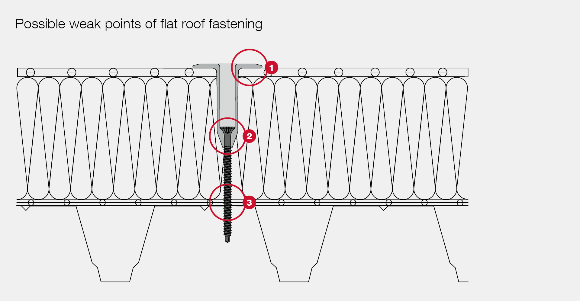
Possible weak points of the flat roof fastening
With the wind uplift test there are three weak points or possible scenarios which could cause a system failure.- The connection between the roofing membrane and the stress plate. This is usually the weakest link of the chain. The failure load largely depends on the mechanical properties of the roofing membrane.
- The connection between the stress plate and the screw. Here, the failure load depends largely on the material of the stress plate and the geometry of the screw head.
- The connection between the screw and the substrate.
The test setup
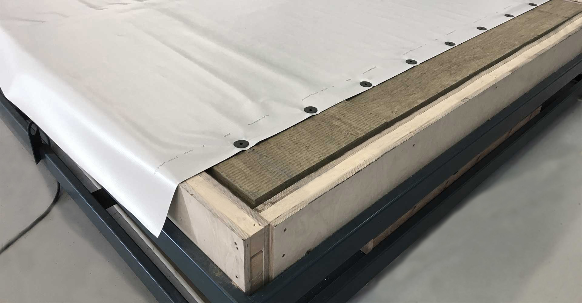
The test setup for the wind uplift test consists of different components and is similar to a test roof setup. For example, a wooden frame is used, which forms the external dimensions of the test item. The frame has the same dimensions as the cover, in which wind suction is generated later. Within this frame there is a steel trapezoidal profile. On top there is 10 cm of insulating material. The roofing membrane is placed on the insulating material and is attached in a defined grid.
The material of the steel trapezoidal profile and the insulation is chosen so that it has a lower grade or is in the area of the most unfavourable property. This guarantees that the test results can also be applied to steel sheets with trapezoidal corrugation that have higher strength properties and insulation with higher compression strength. Once the test roof set-up has been finished, and the overlap of the roofing membrane has been welded, the test is performed under a cover. Under this cover, artificial blasts of wind are now generated. They cause the roofing membrane to bulge upwards.
The quantity, frequency and intensity of the blasts of wind are specifically fixed. A blast of wind lasts 8 seconds and consists of a phase in which the wind suction is built up. This is then maintained for 2 seconds and then further reduced. The next wind suction then begins immediately afterwards. A cycle ends after 1,415 wind blasts. The force is built up slowly during a cycle. The test is performed until there is a failure in the system. A wind uplift test according to EAD or DIN 16002 can take up to three days.
The results
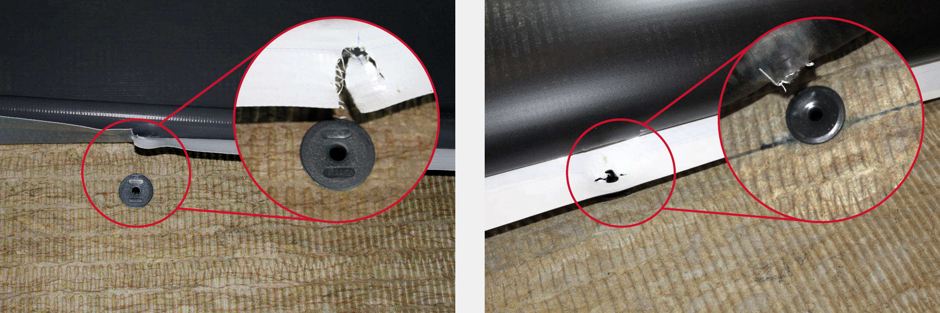
The usual failure pattern of a wind uplift test is tearing (left picture) or pulling over the roofing membrane (right picture). They account for around 90% of all failure cases in a wind uplift test.Another, albeit rare, failure is the fastener being pulled out of the substrate. The frequency of this failure is around 8 per cent. It mainly occurs with enormously strong roofing membranes and is the normal failure with linear rail fixing systems.
Very rare, but also possible, is the roofing membrane being pulled out behind the welded seam. Normally this is due to a processing error when welding the roofing membrane, or a material error in the fabric inserted into the roofing membrane.
Following a wind uplift test, the client receives a test report. This test report firstly describes the system set-up, including all the individual components, and the results are determined with the aid of correction factors and partial safety factors. Afterwards, the test set-up is described using images and the failure is documented.
The rated value of the load-bearing capacity resulting from the test report – this can be reduced again to a certain value depending on a manufacturer's ETA system – is then included in the wind load calculation. We will deal with the wind load calculation according to DIN EN 1991-1-4 in the next part of our guidebook.


